TOOLS FOR SELF DRILL SCREW FORMING MACHINES
DRILL POINT DIES FOR SELF-TAPPER DRILLS FORMING
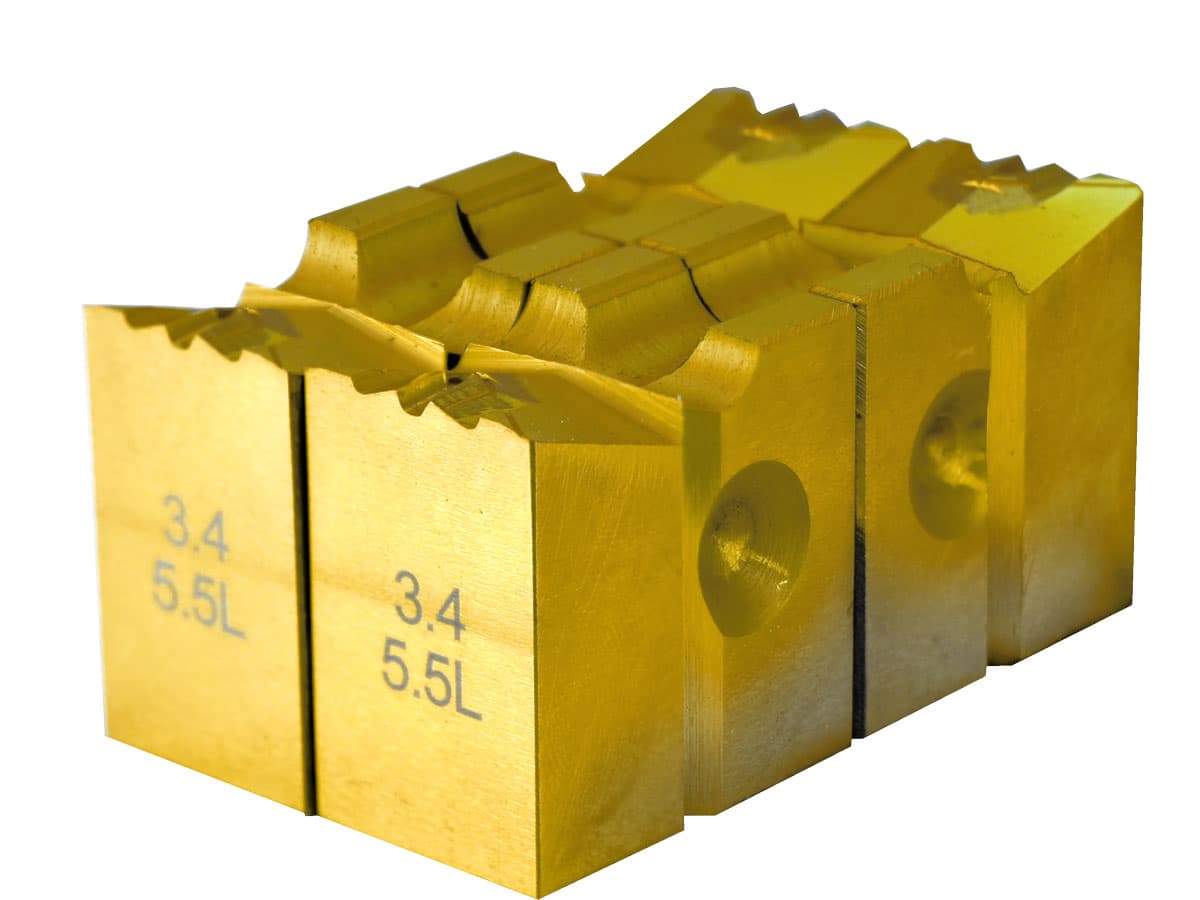
The self-drilling screw is very commonly used as it has a drill point that penetrates into the material quickly without any pilot drill hole. The drill point die is to make the end point of these self-drilling screws. This type of tool is intended mainly for metal screws, but also used for fastening parts from metal profiles, drywall, plastics, chipboard and others, which are divided into several types:
- Pointed black screws that go through the phosphating process
- Galvanized screws
- Hex head screws


Advantages
- Sharp drill point forming: Thanks to the design of high-level precision and the strong material, our drill point dies help to produce screws with sharp points.
- Compatibility with thread rolling machine: as we mentioned before, we offer a great variety of drill point dies in terms of their sizes, materials, and designs, which meet the requirement of different screw point forming machines. We have our own design and development team of dies for different types of screws.
- High-quality control: With a complete system of quality control, we offer you drill point dies with long-service life and more importantly, with high precision, which is the key in the screw forming process.
The main parameters of screws with a drill: diameter 2.8 mm - 10 mm, length 9.5 mm - 210 mm
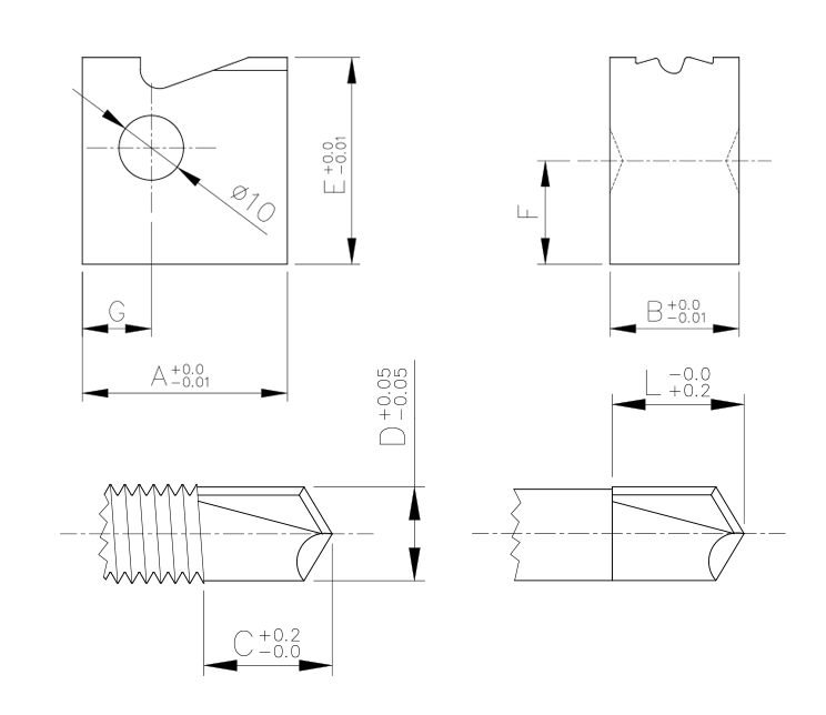
Tool size: 31.75x12.7x25.4 mm; 31.75x20x32 mm or 34 mm; 45x30x32 mm or 34 mm, and also in accordance with the table below or in accordance with the customer's drawings or on the basis of the finished product provided, indicating the seating positions of the machines, the model of the machines used and the diameter of the wire used as raw material for landing fasteners and hardware.
The formation of the drill occurs due to the compression of the tip of the core of the product.
Type of drill: drill, wolfram wing drill
Material: tungsten carbide, high-speed steel M2, SKH 9 / 51
Coating: PVD (vacuum deposition)


Working parameters of the Drill Point Die
| Tool type | Type 1 | Type 2 | Type 3 |
|---|---|---|---|
| Tool appearance | 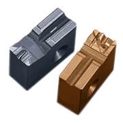 | 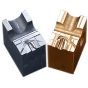 | 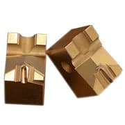 |
| A | 31.75 | 31.75 | 45.00 |
| B | 12.70 | 20.00 | 30.00 |
| E | 25.40 | 32.00 | 32.00 |
| F | 11.4 | 18.0 | 16.0 |
| G | 10.7 | 10.7 | 16.0 |

| Code | Drill diameter | Working length | The length of the drill | Type |
|---|---|---|---|---|
| L1-22 | 2.2 | 2.5 | 1.7 | Type 1 Type 2 |
| L1-23 | 2.3 | |||
| L1-27 | 2.7 | 2.5 3.5 | 2.4 3.2 | |
| L1-28 | 2.8 | |||
| L1-29 | 2.9 | |||
| L1-30 | 3.0 | |||
| L1-31 | 3.1 | |||
| L1-32 | 3.2 | |||
| L1-33 | 3.3 | |||
| L1-34 | 3.4 | |||
| L1-35 | 3.5 | |||
| L1-36 | 3.6 | |||
| L1-37 | 3.7 | 4.2 | 4.0 | |
| L1-38 | 3.8 | |||
| L1-39 | 3.9 | |||
| L1-40 | 4.0 | |||
| L1-41 | 4.1 | |||
| L1-43 | 4.3 | 5.2 | 5.0 | Type 2 |
| L1-45 | 4.5 | |||
| L1-47 | 4.7 | |||
| L1-49 | 4.9 | |||
| L1-51 | 5.1 | 6.4 | 6.2 | |
| L1-53 | 5.3 | |||
| L1-55 | 5.5 | |||
| L1-57 | 5.7 | |||
| L2-22 | 2.2 | 3.2 | 2.2 | Type 1 Type 2 |
| L2-23 | 2.3 | |||
| L2-27 | 2.7 | 3.9 | 3.0 | |
| L2-28 | 2.8 | |||
| L2-29 | 2.9 | |||
| L2-30 | 3.0 | |||
| L2-31 | 3.1 | 4.5 | 3.9 | |
| L2-32 | 3.2 | |||
| L2-33 | 3.3 | |||
| L2-34 | 3.4 | |||
| L2-35 | 3.5 | |||
| L2-36 | 3.6 | |||
| L2-37 | 3.7 | 5.1 | 4.8 | |
| L2-38 | 3.8 | |||
| L2-39 | 3.9 | |||
| L2-40 | 4.0 | |||
| L2-41 | 4.1 | |||
| L2-43 | 4.3 | 6.0 | 5.9 | Type 2 |
| L2-45 | 4.5 | |||
| L2-47 | 4.7 | |||
| L2-49 | 4.9 | |||
| L2-51 | 5.1 | 7.2 | 7.0 | |
| L2-53 | 5.3 | |||
| L2-55 | 5.5 | |||
| L2-57 | 5.7 | |||
| L3-23 | 2.3 | 3.8 | 3.7 | Type 1 Type 2 |
| L3-27 | 2.7 | 4.5 | 3.7 | |
| L3-28 | 2.8 | |||
| L3-29 | 2.9 | |||
| L3-30 | 3.0 | |||
| L3-31 | 3.1 | 5.5 | 4.7 | |
| L3-32 | 3.2 | |||
| L3-33 | 3.3 | |||
| L3-34 | 3.4 | |||
| L3-35 | 3.5 | |||
| L3-36 | 3.6 | |||
| L3-37 | 3.7 | 6.8 | 5.7 | |
| L3-38 | 3.8 | |||
| L3-39 | 3.9 | |||
| L3-40 | 4.0 | |||
| L3-41 | 4.1 | |||
| L3-43 | 4.3 | 8 | 6.7 | Type 2 |
| L3-45 | 4.5 | |||
| L3-47 | 4.7 | |||
| L3-49 | 4.9 | |||
| L3-51 | 5.1 | 9.3 | 8.0 | |
| L3-53 | 5.3 | |||
| L3-55 | 5.5 | |||
| L3-57 | 5.7 | |||
| L4-28 | 2.8 | 5 | 4.5 | Type 1 Type 2 |
| L4-32 | 3.2 | 6 | 5.5 | |
| L4-34 | 3.4 | 7 | 6.2 | |
| L4-39 | 3.9 | 9 | 7.8 | |
| L4-43 | 4.3 | 12.5 | 10.7 | |
| L4-45 | 4.5 | |||
| L4-47 | 4.7 | |||
| L4-49 | 4.9 | |||
| L4-51 | 5.1 | |||
| L4-53 | 5.3 | |||
| L4-55 | 5.5 | |||
| L4-57 | 5.7 | |||
| L5-49 | 4.9 | 15 | 13.7 | Type 1 Type 2 |
| L5-51 | 5.1 | |||
| L5-53 | 5.3 | |||
| L5-55 | 5.5 | |||
| L5-57 | 5.7 | |||
| L6-49 | 4.9 | 17.7 | 16.7 | Type 1 Type 2 |
| L6-51 | 5.1 | |||
| L6-53 | 5.3 | |||
| L6-55 | 5.5 | |||
| L6-57 | 5.7 | |||
Technology
After heading up the head, the semi-finished products to be formed by the drill are loaded into the hopper, which orients the workpieces with the head up, moving them along the guide rulers to the processing zone. There, they are alternately picked up by the rotary mechanism and transferred to the working area, in which the crimping knives are mounted, which, while simultaneously crimping the end of the workpiece, form a drill. The metal flare formed after the compression is further removed during the rolling of the thread onto the self-tapping screw.
Self Drilling Point Forming Dies is used on the following machines: EQUIPMENT FOR DRILLS FORMATION ON SELF-TAPPERS